

|
|
|
||||||||||||||||||||||||||||||||||||||
|
| |||||||||||||||||||||||||||||||||||||||
|
||
Building a custom wood sailboat
|
||
Photos of the 25' Black Skimmer under construction |
||
| If the detail here seems a bit much, please bear with me. This page is not only for you, gentle reader, but also for our client. Anyway, on to the photos: 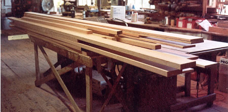 We always say that every boat we build starts with a pile of lumber. Well, here it is. This pile happens to be all vertical grain clear Douglas fir. 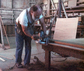 The hull and deck planking of this boat will be plywood. The first thing we'll do is to scarf the side planking. We buy 4X8 sheets and join them together end-to-end with epoxy glued scarf joints. Here, David is cutting the scarfs with a special portable saw attachment. The plywood for this boat will be Brazilian Jequitiba marine plywood, water and boilproof to British 1088 specs. 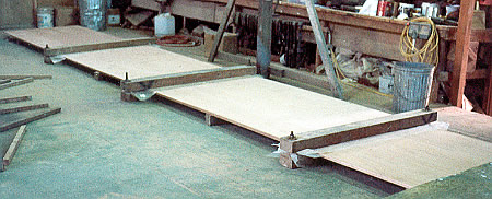 The scarfs are glued up in our shop-built scarfing presses. Those presses are more trick than they appear to be in the picture. 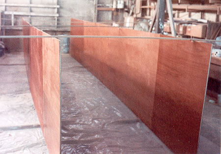 Now we'll give those sheets their last drink: epoxy. Three coats on the inside and glass and epoxy on the outside. 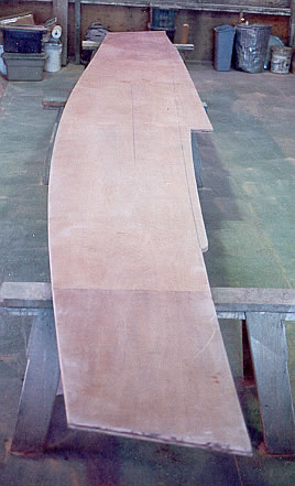 This design is one of Phil's so-called Instant Boats. Believe me, it's not that Instant. In any case, we'll cut out the sides first and then bend them around the bulkhead frames. These are the sides. 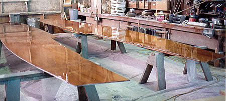 After we cut them out, we covered them with epoxy and glass, and then recoated with more epoxy. They got nice and shiny. Then we sanded and made them all dull again. 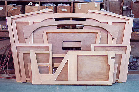 While the sides were taking shape, we were also cutting out and assembling the bulkhead frames. 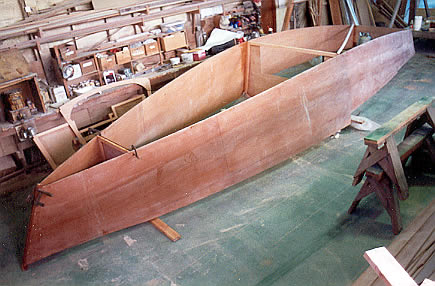 This is the Instant Boat part. We wrapped the sides previously cut out and epoxied around the assembled bulkhead frames. 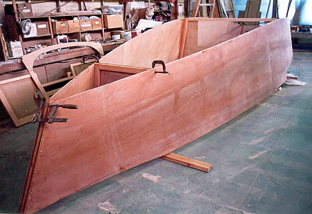 You can see there's quite a bit of volume in this hull. The black line marked on the topsides, just above the floor, is the true sheer. We'll put a guard on that line. The area above the line is the raised deck. 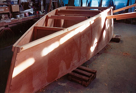 Next we installed the remainder of the bulkheads. Of course the bulkhead centerlines didn't all come out on the hull centerline, so we shored them so that they do line up. Next we installed the chines. Then we'll put the bottom on and that will keep everything lined up. 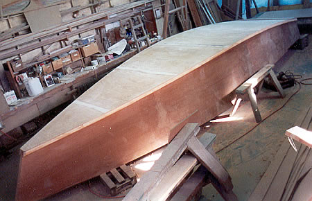 The first layer of the bottom is installed. We faired the seams and then ground a little hollow at each seam, which we filled with epoxy putty. We are making the bottom airtight because we will vacuum bag the second layer of bottom, instead of using fasteners. 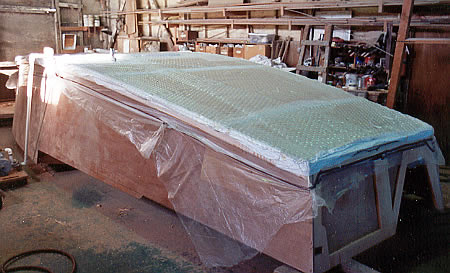 Here's a photo of the bagging process. There's about 10psi air pressure pushing down on the bottom, and of course the same 10psi pushing up on the inside of the inner layer of the bottom. Nancy and I had the bottom on and a vacuum pulled in about two hours. 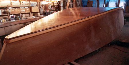 After we smoothed the bottom up and rounded the corners, we gave it a drink of epoxy. When this cures, we'll glass it, stopping the glass about halfway down the chines. We were pleased at how fair the outer layer turned out. 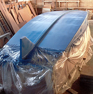 After glassing and sanding smooth (not photogenic work), we installed the skeg and put on a coat of antifouling paint. The final antifouling will be red. This blue coat will enable the owner to see when his red antifouling is getting thin, while still having a layer of protection. We glued that skeg up out of clear VG fir, faired it to an airfoil shape, and glassed it. It has four pieces of threaded bronze rod embedded in epoxy, set up with nuts on the inside of the bottom, to hold it on. 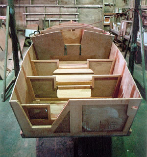 Taken immediately after rolling the hull over, this photo shows part of the rollover jig with its hand winches and cables still attached to the boat. The cockpit bulkheads are ready to receive the remaining cockpit structure and came out perfectly lined up, which is pretty cool. The notch in the transom is for the outboard and the hole to starboard is for the boomkin. 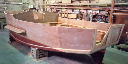 Here she is with the final red bottom paint. We've attached her "wings" - leeboards rest against these, and we've continued framing in the cockpit. 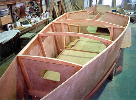 Looking into the cabin, we've got the berth plywood installed. The cabin sole plywood has been installed in sections for easy removal. We've started building a pair of galley cabinets. One of the toekicks is visible. 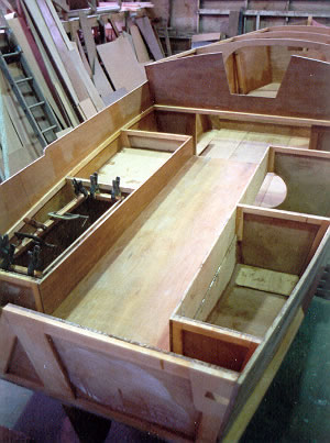 The footwell plywood is in. We've installed the plywood icebox and have finished bulkheading off the foam compartments, into which we will pour urethane foam for flotation. Because the icebox will take up some of the foam space, we will pour some into the next port compartment forward to make up for it. 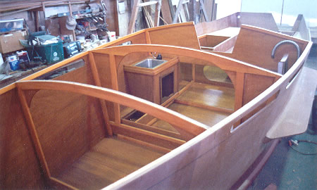 The galley cabinets have been installed and the interior finish applied. We've installed a deep SS sink and flipper pump. A flexible water tank will be installed under the bridge deck in its own compartment. The small compartments forward of the cabinets are seats with hinged tops. The seat tops, cabinet doors, berth flat, cabin sole, and other interior parts are finished but won't be installed until the boat is finished. We used Cetol Marine for the interior finish. 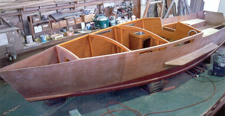 Same thing as the photo above, but from further away so you can get a better idea of what's what. 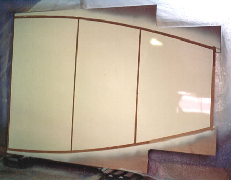 We scarfed up the cabin top into a single piece, masked off the beams and cabin sides, and painted it with Awlgrip. We'll cut it out after it's installed, so we'll have better leverage when we pull it down onto the cabin sides. We'll also cut out the companionway after installation, so the cabin top will bend into place fairly. 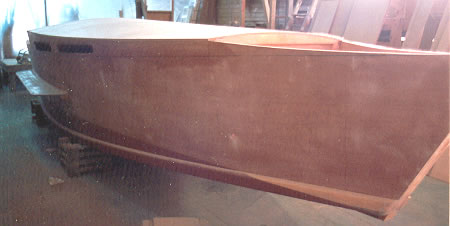 Here's what she looks like with the cabin top installed and cut out. 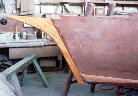 Next, the Skimmer gets a beak. 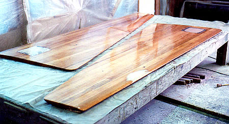 We built the leeboards from laminated vertical grain Douglas fir. We shaped them into asymmetrical airfoil sections. Each board is ballasted with about 35 lbs. of lead, cast in place after the boards were faired. This photo shows the leeboards getting their final drink of epoxy. We then covered them with two layers of 6 oz. glass cloth. 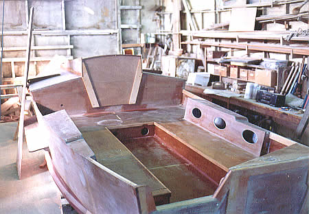 Here we've decked and trimmed the cockpit. We've added seat back compartments to the cockpit design, to improve seating geometry and add some cockpit storage. These seat backs have their aft ends located as shown because the mizzen sheet outrigger jams into its socket there. We ended these compartments even with the forward end of the footwell. That preserves the fine lounging area on the bridge deck and makes it simpler to get rid of water that might collect at the forward end of the bridge deck while the skipper is sleeping. We can put a stern cleat at the very aft end of these compartments, and put cam cleats for the leeboard tackles on their tops. The tops are crowned the same as the cabin top. That makes the seat backs higher than the hull sides, and will provide a level surface for sitting when the boat is heeled. That's a leeboard just leaning against the port hull side. 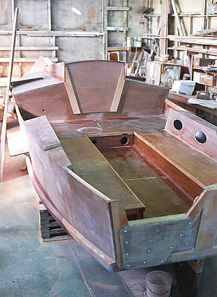 Another, similar view of the cockpit, showing the raised and strengthened outboard cutout in the transom. We'll use an 8 HP Yamaha High Thrust outboard. Outboards were smaller 25 years ago, when this boat was designed. 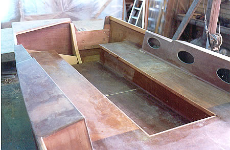 A view of the cockpit from forward shows the heavy transom knee we added to stiffen the transom against the stresses of both the outboard and the mizzen mast. Phil's original transom knee was reported to be much too small. We can also see an angled fir plank on which we will chock the Danforth stern anchor. 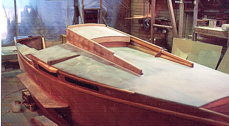 This photo gives a view of the companionway hatch structure. Besides the waterstops/braces that you can plainly see on the inboard sides of the hatch runners, we also added some waterstops beside the inner coamings, so that any water taken over the bow can't find its way into the cabin. 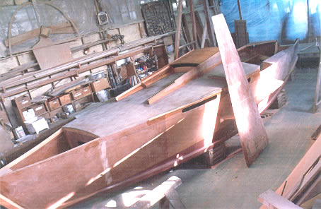 A leeboard leans against the hull. When deployed, the top of the leeboard will be about even with the cabin top. 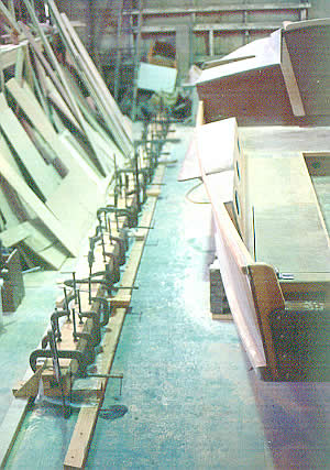 Gluing up the mast. We built a "mast bench" on the floor, shimmed to be straight and level. You can see that what you need to glue up spars is lots of clamps. There are other ways, but clamps are mighty convenient. 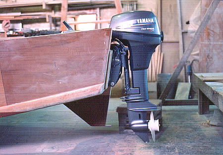 This may not be the world's greatest sailboat at going upwind in a big chop in San Fransisco Bay, so we decided to fit an 8 HP Yamaha high thrust 4-stroke motor. The prop is well immersed. This should take care of any eventuality. 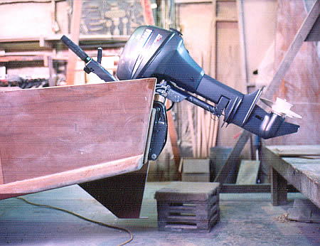 When the motor is tilted up, it will add a good bit of length to the package. 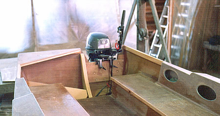 Here we see the motor from inside the cockpit. The motor cutout shown in Bolger's drawings reflects the size of outboards available 20 years ago. They've gotten a lot bigger, so we raised and thus also widened the cutout to suit this motor. 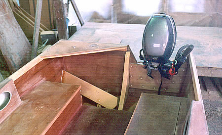 Just showing that the motor clears everything when tilted up, also. We added a large transom support knee to starboard of the motor cutout. This knee will also keep the mizzen mast from flexing the transom top, which is a problem if you build it as designed. That chunk of VG Fir 2X6 to starboard will hold anchor chocks for the Danforth stern anchor. 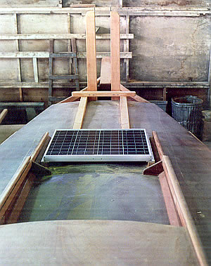 Since this boat will be used for some cruising and the outboard may almost never get used, the owner specified a solar battery charging system. This solar panel just fits forward of the opened hatch. We also built a strong wooden cover for the solar panel, as it will be necessary to walk there when raising the mast from its horizontal trailering position. 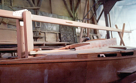 This shows the mast in the lowered position, supported by a set of boom scissors in the cockpit. 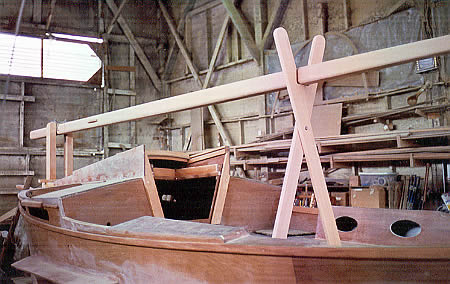 A view of the lowered mast from aft. 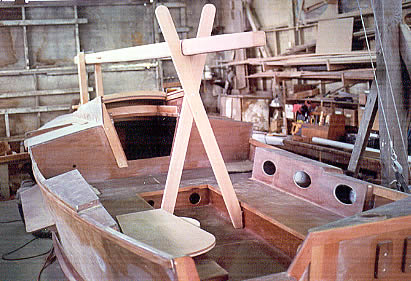 Showing how the mast scissors are mounted in the cockpit, positioned between small cleats on the sides of the footwell. The scissors form a fork above the mast to corral the rest of the spars for trailering. That's the rudder blade sitting in the cockpit near the scissors. 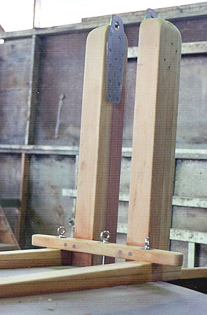 Here's the finished tabernacle with hardware. The eyebolts are epoxied in place and will have various blocks attached to them to take the running rigging aft to the cockpit. The stainless steel tabernacle pivot plates are also epoxy bonded. There will be cleats on the outside faces of the tabernacle, high up. You can see we've drilled for them, but we won't epoxy bond them until after the boat is undercoated. 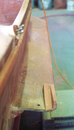 We added this little block to the aft end of the leeboard "wings" to hold the leeboards solidly when trailering. This leeboard positioning also keeps the trailering width under 8'6". 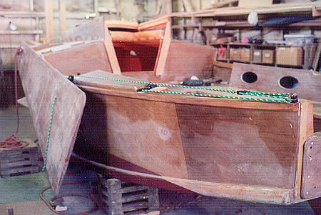 Three part leeboard tackle is the way to go for this boat. A good compromise between ease and speed. The leeboard is shown in what will be the raised position when sailing. 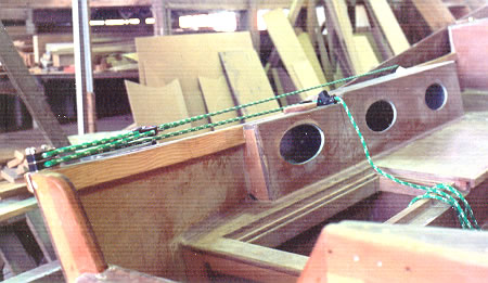 Another view of the leeboard tackle. A rope clutch holds the line nicely and is easy to release. We always dry fit hardware before painting, to make sure that everything will work. 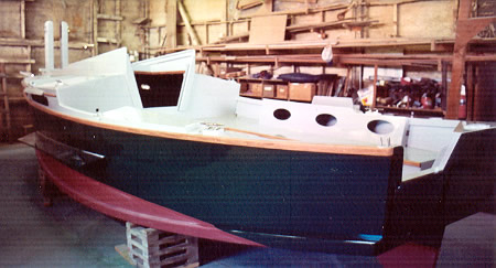 So, everything being all done and fitted, we painted the boat. That's Awlgrip Jade Mist Green on the hull and Awlgrip Light Gray on the deck and cockpit. 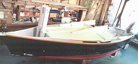 Here's the same thing, shot from above. Now it's time to start installing hardware permanently! After hardware installation and wiring, the construction phase is finished. |
We are located on the Snohomish River in the Pacific Northwest, about 20 miles north of Seattle.
Click here for a map to Nexus Marine Corporation.
| Home | The Boats | Boat Plans | About Nexus | Why Wood | FAQ | Links |
|
Exterior Photos Interior Photos Sailing Photos |